3 Benefits of Using GD&T in CNC Machining
What is Geometric Dimensioning and Tolerancing?
Geometric Dimensioning and Tolerancing, abbreviated as GD&T, is a system for defining and communicating design intent and engineering tolerances in manufacturing. GD&T is a language of symbols and standards that describes any part dimensions and its allowable variation in size, form, orientation, and location.
Why Use GD&T in Complex CNC Machining?
There are 3 benefits of using GD&T in complex CNC machining.
1. Enhanced Communication:
GD&T allows you to convey substantial information about your part’s design using a relatively small amount of letters, numbers, and symbols. The use of a single and standardized GD&T language ensures engineering, design, production, and quality teams are able to communicate clearly and accurately with each other, saving time and increasing efficiency.
2. Accurate Production:
Since GD&T is such a precisely articulated system of language, it minimizes ambiguity in the description of a part’s design. Part production becomes more repeatable and consistent – simplifying inspection, reducing the part rejection rate, and improving quality.
3. Increased Flexibility:
GD&T specifies the design intent instead of the specific geometry, providing the appropriate tolerances that maximize production. It results in more manufacturing flexibility and larger tolerances, especially for intricate or complex designs!
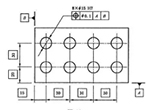
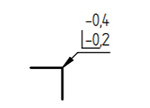
Geometric tolerancing reference chart
Within GD&T, “geometric” refers to various form, such as a plane, cylinder, or square.Below are examples of the geometric characteristics and corresponding symbols as well as the nomenclature commonly used with GD&T.
|
Geometric Tolerance Symbol |
||||
| Types of | Geometric | Symbols | Datum | Sample Graphs |
| Form | Straightness | No | 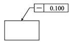 |
|
| Flatness | No | 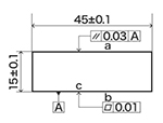 |
||
| Circularity | No | 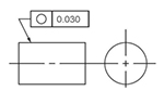 |
||
| Cylindricity | No | 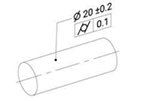 |
||
| Profile | rofile of a Line | Yes or No | 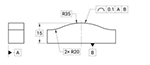 |
|
| Profile of a Surface | Yes or No | 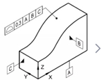 |
||
| Orientation | Parallelism | Yes | 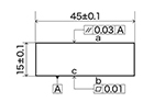 |
|
| Perpendicularity | Yes | 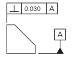 |
||
| Angularity | Yes | 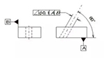 |
||
| Location | Position | Yes or N | 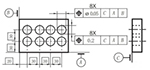 |
|
| Concentricity | Yes | 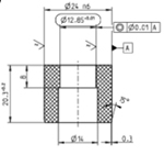 |
||
| Symmetry | Yes | 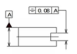 |
||
| Run-out | Circular Run-out | Yes | 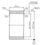 |
|
| Total Run-out | Yes | 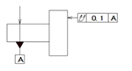 |
||
| Additional Symbols | Datum Symbol and code | Yes | 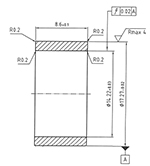 |
|
| Datum Target | Yes |  |
||
| Maximum Material condition | 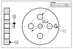 |
|||
| Envelope Requirement | 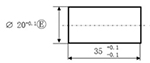 |
|||
| Projected Tolerance Zone | 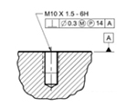 |
|||
 |
||||
| Not concave, Not convex, Only allowed to decrease in small end direction. |
 |
 |
||
Need has been providing one-stop service solution for precision parts utilizing our advanced machining capabilities and production facilities serving the automotive, electronics, medical, and automation industrial markets. Contact us today to learn more about our complete manufacturing solutions.